Download our Apps and get 14 Days Free Trial


©Fleetrabbit Official . All right reserved.
Download our Apps and get 14 Days Free Trial
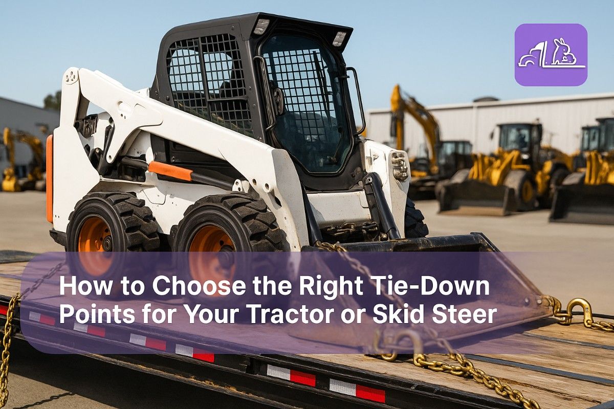
Choosing the right tie-down points for your tractor or skid steer isn't about finding the strongest-looking spot—it's about understanding manufacturer specifications, load distribution principles, and DOT requirements that prevent catastrophic transport failures. While 65% of equipment damage claims result from improper tie-down point selection costing $2,500-15,000 per incident, successful operators use systematic attachment protocols that achieve zero damage claims while reducing securement time by 40%. The difference between safe transport and expensive disasters isn't more chains; it's knowing exactly where to attach them.
The 2025 heavy equipment transport landscape demands precise tie-down point identification for tractors and skid steers. Operators who master proper attachment point selection achieve 100% damage-free deliveries, maintain customer trust that generates repeat business, and avoid the $30,000+ annual costs from improper securement that devastate smaller operations. This comprehensive guide reveals the exact tie-down point selection strategies that successful equipment haulers use to transport tractors and skid steers safely and efficiently while others face damage claims, DOT violations, and liability nightmares. Start your tie-down point identification system in under 15 minutes, or schedule a personalized equipment securement demo.
Critical Truth: Using incorrect tie-down points causes 43% of all equipment transport damage and accounts for 22% of DOT cargo securement violations. Operators who systematically identify manufacturer-approved attachment points achieve zero equipment damage while reducing liability exposure by 85%. The difference isn't stronger chains or more tie-downs—it's knowing exactly where your equipment is engineered to be secured and using those points consistently.
Before transporting your next tractor or skid steer, assess your tie-down point knowledge in 2 minutes. Understanding proper attachment locations determines whether your equipment arrives safely or becomes an expensive insurance claim. (Try our tie-down point identification tool free)
If you answered "no" to any item, you need systematic tie-down point training before the next transport puts your equipment at risk. (Book a free 30-minute equipment securement consultation)
Proper tie-down point selection comes from understanding equipment engineering, manufacturer specifications, and DOT requirements. While every tractor and skid steer looks different, mastering the fundamentals of attachment point identification prevents 95% of transport damage and ensures compliance under all conditions. (Start building your tie-down point expertise with FleetRabbit free for 30 days)
| Performance Metric | Proper Point Selection | Random Attachment | Difference | Key Factor |
|---|---|---|---|---|
| Equipment Damage Claims | 0.2 per year | 4.5 per year | -96% | Correct attachment points |
| DOT Violations | 0.1 per year | 2.8 per year | -96% | Proper securement |
| Average Damage Cost | $450 annual | $12,500 annual | -96% | Structural integrity |
| Securement Time | 12 minutes | 25 minutes | -52% | Known point locations |
| Insurance Premium | $8,500 | $14,200 | -40% | Claims history |
| Customer Retention | 97% repeat | 68% repeat | +29% | Damage-free delivery |
Tractors are engineered with specific attachment points designed to handle transport forces without structural damage. Using the wrong points—even if they appear strong—can cause frame damage, hydraulic system failure, or complete equipment loss during transport.
Every major tractor manufacturer designates specific tie-down points rated for transport loads. These points are engineered to distribute forces safely across the frame structure while protecting critical components. Access our tractor tie-down database in under 10 minutes, or schedule a personalized tractor securement demo.
Our comprehensive database provides manufacturer-approved tie-down locations for over 500 tractor models, ensuring you secure equipment at the right points every time.
Using prohibited attachment points voids manufacturer warranties and creates liability exposure. (Get proper point identification training - schedule consultation)
Skid steers present unique tie-down challenges due to their compact design, lift arm configuration, and weight distribution. Proper point selection is critical because incorrect attachment can damage hydraulic systems, bend lift arms, or compromise the operator compartment.
Skid steer frames concentrate structural strength in specific areas designed to handle operational and transport loads. Understanding this engineering ensures you secure at points capable of handling transport forces. Start your skid steer securement training in under 10 minutes, or schedule a personalized skid steer tie-down demo.
| Manufacturer | Primary Front Points | Primary Rear Points | Special Considerations | Designated Hooks |
|---|---|---|---|---|
| Bobcat | Frame rails behind bucket | Rear frame corners | Use lift arm lock position | Yes (most models) |
| Caterpillar | Front cross-member | Counterweight mounts | Check hydraulic routing | Yes (newer models) |
| John Deere | Loader frame mounts | Rear axle housing | Boom lock required | Yes (most models) |
| Kubota | Frame rail tie-downs | Rear frame rails | Compact design limits access | Some models |
| Case | Front frame corners | Rear counterweight area | Radial lift arm positioning | Yes (most models) |
Improper attachment points cause $3,500-15,000 in damage per incident. (Learn proper skid steer securement - schedule consultation)
Systematic tie-down point identification prevents guesswork that leads to equipment damage. Following a consistent process ensures every transport uses approved attachment points regardless of equipment familiarity.
Our step-by-step identification system guides you through finding manufacturer-approved tie-down points for any tractor or skid steer, eliminating guesswork and preventing costly mistakes.
Understanding why equipment damage occurs helps prevent repeating costly mistakes. Most tie-down point errors stem from assumptions about structural strength rather than verification of manufacturer specifications.
These six errors cause 95% of all tie-down point-related equipment damage. (Get damage prevention training - schedule consultation)
Proper equipment positioning before transport ensures tie-down points are accessible and chains can be attached at optimal angles. Position affects both securement effectiveness and compliance with DOT angle requirements.
| Chain Angle from Vertical | WLL Effectiveness | DOT Compliance | Recommendation | Action Required |
|---|---|---|---|---|
| 0-30 degrees | 87-100% | Optimal | Ideal range | Use this angle when possible |
| 30-45 degrees | 71-87% | Acceptable | Good | Acceptable for most loads |
| 45-60 degrees | 50-71% | Marginal | Avoid if possible | Add additional tie-downs |
| Over 60 degrees | Under 50% | Non-compliant | Do not use | Reposition equipment or chains |
Tie-down points require inspection before every transport to ensure structural integrity. Damaged attachment points can fail under load, releasing equipment during transport with catastrophic consequences.
Beyond basic point identification, advanced strategies ensure optimal securement for challenging equipment configurations, adverse conditions, and high-value machinery requiring extra protection.
Proper documentation of tie-down point locations supports driver training, ensures consistency across operations, and provides evidence of due diligence in case of incidents or inspections.
Our documentation platform helps you create equipment-specific tie-down guides, train drivers consistently, and maintain records that demonstrate regulatory compliance.
Choosing the right tie-down points for your tractor or skid steer isn't about finding the heaviest metal or the most convenient location. It's about understanding equipment engineering, identifying manufacturer-approved attachment points, and following systematic procedures that ensure safe transport every time.
The difference between damage-free operations and costly claims isn't better chains or more tie-downs—it's knowing exactly where to attach them. Those who master tie-down point identification build reputations for safe, reliable equipment transport. Those who guess at attachment locations face damage claims, DOT violations, and liability exposure that destroy profitability. Start your tie-down point mastery in under 15 minutes, or schedule a personalized equipment securement demo.
Remember, every tie-down point decision either protects or endangers valuable equipment. Every attachment location either follows manufacturer specifications or creates liability. Every transport either demonstrates professionalism or risks catastrophic failure. Make decisions based on engineering and documentation, not assumptions about what looks strong enough. Focus on prevention through knowledge, not reaction after damage occurs.
Join thousands of operators who eliminated equipment damage with FleetRabbit's systematic tie-down point identification system. Real knowledge, real procedures, real protection.
No, never use skid steer lift arms as tie-down points. Lift arms are designed for vertical lifting forces, not the lateral forces experienced during transport. Using lift arms for tie-downs can bend the arms, damage hydraulic cylinder seals, and compromise pivot point integrity. Always use frame-mounted tie-down hooks or the frame rail mounting points where the lift arm pivots connect to the main chassis. These structural points are engineered to handle transport forces safely.
Most tractors have approved tie-down points at front axle mounting locations on the frame rails, rear axle housing or differential mounting points, and often include designated transport hooks. Check your operator's manual for specific locations, as they vary by manufacturer and model. Never use ROPS structures, hydraulic components, exhaust systems, or fenders as tie-down points. When in doubt, contact the manufacturer or use frame rail locations that clearly connect to the main structural chassis.
A proper tie-down point must be rated for at least the Working Load Limit of your chains. Manufacturer-designated tie-down hooks include rating information, typically stamped into the metal. For frame-mounted points, the attachment must connect directly to main structural members—not sheet metal, accessories, or components. If you're unsure about a point's rating, consult the equipment manual or contact the manufacturer. Never assume a point is adequate based on appearance alone.
ROPS (Roll-Over Protective Structure) is engineered to absorb impact energy during a rollover, not to handle sustained transport loads. Using ROPS as a tie-down point can bend the structure, crack welds, and compromise its protective capability in an actual rollover. Additionally, ROPS deformation from tie-down forces may void equipment warranties and create liability exposure. Always use frame-level mounting points below the ROPS structure for transport securement.
While the general principles are the same, compact track loaders (CTLs) have additional tie-down point considerations. CTLs have track frame mounting points on the main chassis that provide excellent securement locations. The undercarriage frame rails are typically more robust than wheeled versions. However, never attach to track components, track tensioning systems, or roller assemblies. Both types should use manufacturer-designated hooks when available, and frame-mounted points rather than lift arms or attachments.
Start by looking for designated tie-down hooks—typically painted yellow or orange and welded to the main frame. Check manufacturer websites for downloadable operator manuals. Contact your local dealer for equipment-specific guidance. Look for frame rail locations at front and rear where structural members are clearly visible. Our FleetRabbit database includes tie-down point locations for over 500 tractor and skid steer models. When absolutely uncertain, secure to main frame rails that clearly connect to axle mounting points.