Master truck electrical troubleshooting with systematic diagnostic methods, professional safety protocols, and proven solutions for the most common commercial truck electrical problems - reduce diagnostic time by 60% and prevent costly electrical failures
85%
Electrical Issues Prevent Truck Starts
$2,400
Average Electrical Repair Cost
60%
Faster Diagnosis with Systematic Approach
12-24V
Standard Commercial Truck Systems
Electrical problems account for 85% of no-start conditions in commercial trucks and represent some of the most challenging diagnostic scenarios in heavy-duty repair. From parasitic battery drain that strands drivers to complex CAN bus communication failures that trigger multiple fault codes, electrical issues require systematic troubleshooting approaches that combine technical knowledge with proper safety protocols. Modern trucks contain over 100 electronic control units (ECUs) connected through miles of wiring, making electrical diagnosis both critical and complex. Whether you're dealing with a simple blown fuse or a sophisticated multiplex wiring failure, mastering electrical troubleshooting saves time, reduces costs, and prevents dangerous roadside breakdowns. Access our electrical diagnostic flowcharts - start troubleshooting in 5 minutes, or schedule a personalized electrical troubleshooting consultation to solve your most challenging electrical problems.
Understanding Commercial Truck Electrical Systems
Modern commercial trucks operate on complex multi-voltage electrical systems that power everything from engine management to driver comfort features. Understanding system architecture is essential for effective troubleshooting and prevents costly diagnostic mistakes. Download our electrical system reference guide - ready in 8 minutes or book an electrical systems training session.
Commercial Truck Electrical System Overview
| System Component | Voltage Range | Current Capacity | Primary Function | Common Failure Modes | Diagnostic Tools | Safety Considerations |
|---|---|---|---|---|---|---|
| Battery System | 12V/24V DC | 100-200Ah | Starting, auxiliary power | Cell failure, sulfation, corrosion | Load tester, hydrometer | Acid burns, hydrogen gas |
| Charging System | 12V/24V DC | 160-320A output | Battery charging, system power | Diode failure, brush wear, regulator | Oscilloscope, amp clamp | Belt hazards, hot components |
| Starting System | 12V/24V DC | 1,500-3,000A peak | Engine cranking | Solenoid failure, brush wear | Current probe, voltage drop | High current arcing |
| Lighting System | 12V/24V DC | 5-55A circuits | Visibility, legal compliance | Corrosion, vibration damage | Multimeter, test light | Hot filaments, UV exposure |
| Engine Management | 5V-12V DC | Low current signals | Fuel, ignition, emissions control | Sensor drift, CAN bus faults | Scan tool, oscilloscope | ESD damage, contamination |
| Air Brake System | 12V/24V DC | 10-30A circuits | Brake control, ABS | Valve coil failure, sensor faults | Pressure gauges, scan tool | Pressurized air, brake safety |
| Trailer Interface | 12V DC | 40-60A total | Trailer lights, brakes, ABS | Connector corrosion, chafing | Trailer tester, multimeter | Weather exposure, contamination |
Essential Electrical Knowledge Areas
- Ohm's Law Applications: Understanding voltage, current, and resistance relationships
- Circuit Types: Series, parallel, and series-parallel configurations
- Wiring Diagrams: Reading schematic symbols and trace circuit paths
- Grounding Systems: Chassis ground, isolated ground, and ground loops
- Protection Devices: Fuses, circuit breakers, and fusible links
- Communication Networks: CAN bus, J1939, and multiplexing systems
Master Truck Electrical Systems
Build comprehensive electrical troubleshooting skills with our systematic training programs. Learn to diagnose problems faster and more accurately using professional techniques.
Systematic Troubleshooting Methodology
Successful electrical troubleshooting follows a logical sequence that prevents wasted time and avoids component damage. Professional technicians use proven diagnostic procedures that isolate problems efficiently and accurately.
Professional Electrical Diagnostic Process
Step 1: Information Gathering
- Document customer complaint and symptoms
- Record environmental conditions and timing
- Review maintenance history and recent repairs
- Check for active fault codes and freeze frame data
- Verify problem reproduction procedures
Step 2: Visual Inspection
- Examine wiring for physical damage or corrosion
- Check connections for looseness or contamination
- Inspect fuses and circuit breakers for damage
- Look for evidence of overheating or arcing
- Document findings with photos for reference
Step 3: Circuit Analysis
- Obtain accurate wiring diagrams for the system
- Identify circuit components and their relationships
- Determine normal operating parameters
- Plan diagnostic test sequence and access points
- Select appropriate test equipment and procedures
Advanced Diagnostic Techniques
Step 4: Electrical Testing
- Measure voltage, current, and resistance values
- Perform voltage drop tests on high-current circuits
- Check continuity and isolation between circuits
- Test component operation under load conditions
- Verify signal integrity with oscilloscope analysis
Step 5: Problem Isolation
- Use divide-and-conquer approach to narrow scope
- Substitute known-good components when possible
- Isolate circuits to eliminate variables
- Compare readings to specification ranges
- Document test results for verification
Step 6: Repair Verification
- Test repair under various operating conditions
- Verify that related systems function properly
- Clear fault codes and confirm no return
- Road test to validate real-world operation
- Document repair procedures and findings
Diagnostic Efficiency
Following systematic troubleshooting procedures reduces diagnostic time by 60% compared to random testing approaches. Professional techniques prevent component damage and ensure accurate repairs the first time.
Common Electrical Problems and Solutions
Understanding the most frequent electrical issues and their root causes enables faster diagnosis and prevents recurring problems. These solutions address 80% of commercial truck electrical complaints. Access our electrical problem database - search solutions in 3 minutes or discuss complex electrical issues.
Top Electrical Problems in Commercial Trucks
| Problem Category | Common Symptoms | Probable Causes | Diagnostic Tests | Typical Solutions | Prevention Methods | Repair Cost Range |
|---|---|---|---|---|---|---|
| Battery/Charging Issues | Slow cranking, dim lights, dead battery | Bad alternator, parasitic drain, old batteries | Load test, amp draw test, voltage drop | Replace alternator, find drain source, new batteries | Regular testing, clean terminals, load management | $200-$2,500 |
| Starting System Faults | No crank, intermittent start, grinding noise | Starter failure, solenoid problems, connections | Voltage drop test, current draw, bench test | Rebuild starter, replace solenoid, clean connections | Proper cranking procedures, clean connections | $300-$1,800 |
| Lighting Circuit Problems | Lights not working, dim operation, flickering | Corroded connections, bad grounds, switch failure | Voltage measurements, continuity tests, load testing | Clean connections, repair grounds, replace switches | Dielectric grease, regular inspections | $50-$800 |
| Trailer Wiring Issues | Trailer lights inoperative, ABS faults | Corroded gladhands, damaged cables, poor grounds | Trailer tester, ohmmeter, visual inspection | Replace connectors, repair cables, improve grounds | Regular connector maintenance, protective covers | $100-$1,200 |
| Engine Control Problems | Check engine light, poor performance, fault codes | Sensor failure, wiring damage, ECU problems | Scan tool diagnostics, signal analysis, substitution | Replace sensors, repair wiring, reprogram ECU | Protect wiring, use quality parts, regular updates | $150-$3,500 |
| Air Brake Electrical | ABS lights, valve malfunctions, poor braking | Valve coil failure, sensor problems, connections | Pressure tests, resistance measurements, visual | Replace valves, clean sensors, repair connections | Keep systems clean, protect from moisture | $200-$2,000 |
| Communication Faults | Multiple system faults, erratic operation | CAN bus problems, termination issues, interference | CAN bus analyzer, oscilloscope, termination tests | Repair CAN wiring, replace terminators, shield cables | Protect CAN networks, avoid aftermarket interference | $300-$4,000 |
COSTLY MISTAKES:
Random parts replacement without proper diagnosis costs fleets an average of $1,200 per electrical problem. Always test before replacing components, and verify repairs solve the root cause, not just the symptom.
Professional Repair Best Practices
- Quality Components: Use OEM or equivalent parts with proper specifications
- Proper Connections: Crimp and solder joints to manufacturer standards
- Environmental Protection: Seal connections against moisture and contaminants
- Wire Routing: Secure wiring away from heat sources and moving parts
- Documentation: Record repair procedures and test results for reference
Essential Diagnostic Tools and Equipment
Professional electrical diagnosis requires the right tools for accurate measurements and safe testing procedures. Understanding tool capabilities and limitations ensures efficient troubleshooting and prevents equipment damage.
Professional Electrical Diagnostic Equipment
| Tool Category | Specific Equipment | Measurement Capability | Typical Applications | Price Range | Skill Level Required |
|---|---|---|---|---|---|
| Digital Multimeter | Automotive DMM with min/max | 0-1000V, 0-40A, 0-40MΩ | Basic voltage, current, resistance tests | $150-$800 | Basic |
| Oscilloscope | 4-channel automotive scope | DC-20MHz, 4 isolated channels | Signal analysis, CAN bus, sensors | $2,000-$15,000 | Advanced |
| Load Tester | Carbon pile or electronic | 500-1000A load capacity | Battery and charging system testing | $400-$2,500 | Intermediate |
| Scan Tool | Heavy-duty capable scanner | J1939, J1587, proprietary protocols | Fault codes, data parameters, calibrations | $3,000-$25,000 | Intermediate |
| Current Clamp | AC/DC current probe | 0.1-3000A measurement range | Non-invasive current measurement | $200-$1,500 | Basic |
| Insulation Tester | Megohmmeter with multiple ranges | 250V-5kV test voltage | Cable integrity, motor windings | $300-$2,000 | Advanced |
| Trailer Tester | 7-pin and 15-pin capability | All trailer circuit functions | Trailer electrical validation | $500-$3,000 | Basic |
Optimize Your Diagnostic Capabilities
Build a complete electrical troubleshooting toolkit with expert recommendations for tools, training, and best practices. Reduce diagnostic time and improve repair accuracy.
Battery System Diagnosis and Maintenance
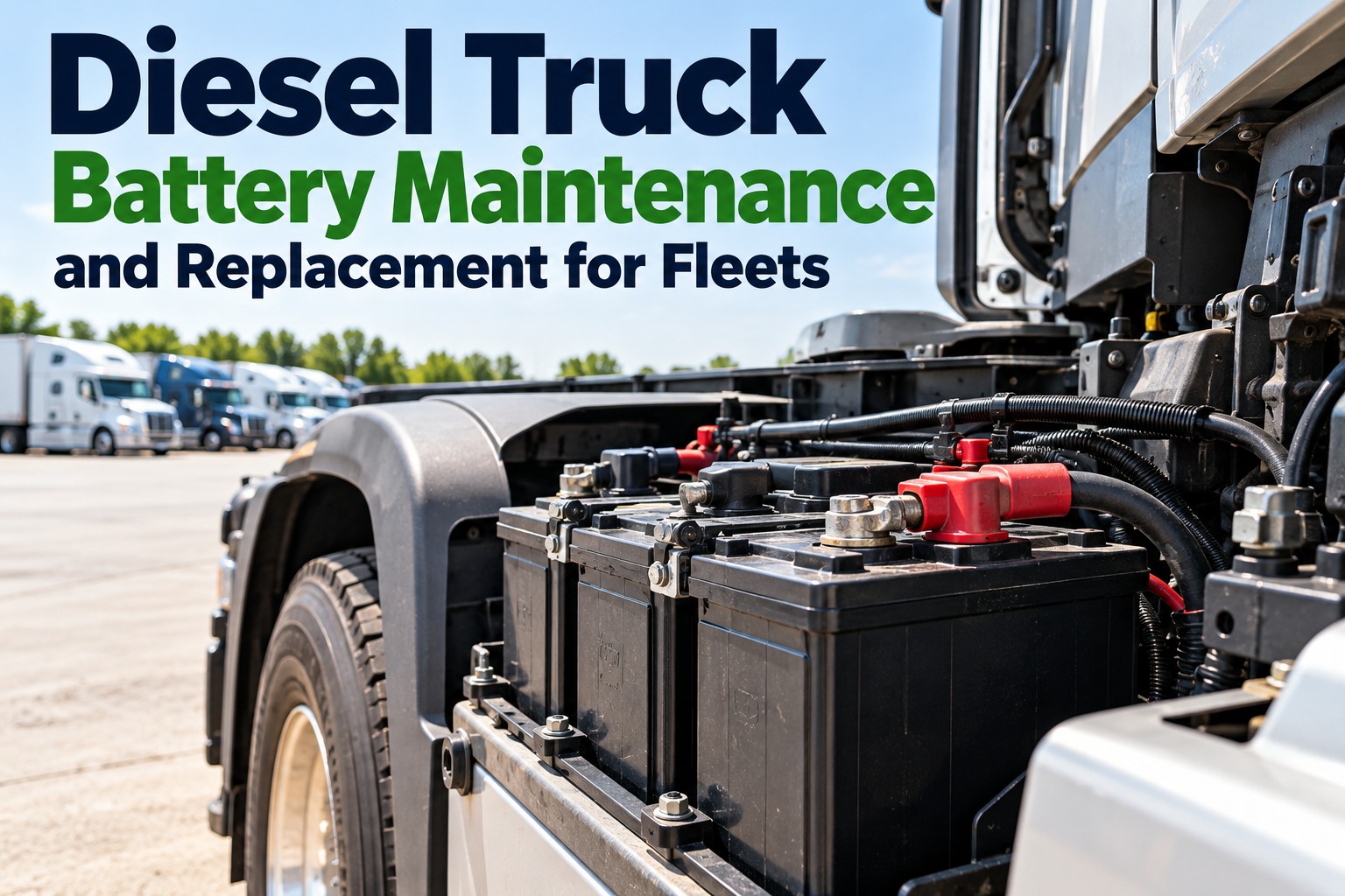
Battery and charging system problems cause more than 60% of electrical service calls. Understanding battery chemistry, charging requirements, and system interactions prevents most charging-related breakdowns.
Commercial Truck Battery System Analysis
| Battery Type | Voltage Configuration | Capacity Range | Life Expectancy | Maintenance Requirements | Common Failure Modes |
|---|---|---|---|---|---|
| Flooded Lead-Acid | 12V (6-cell) or 24V series | 100-200Ah | 3-5 years | Water level, equalization charging | Sulfation, plate corrosion, water loss |
| AGM (Absorbed Glass Mat) | 12V (6-cell) or 24V series | 80-180Ah | 4-6 years | Minimal, proper charging voltage | Thermal runaway, grid corrosion |
| Gel Cell | 12V (6-cell) deep cycle | 75-150Ah | 5-7 years | Temperature compensation, low charging rates | Gel separation, overcharging damage |
| Lithium Iron Phosphate | 12V (4-cell) with BMS | 100-300Ah equivalent | 8-12 years | BMS monitoring, temperature control | Cell imbalance, thermal protection faults |
Parasitic Drain Testing
Normal Draw: Less than 100mA after 60 minutes
Test Method: Amp clamp on negative cable
Common Sources: Radio memory, ECU keep-alive
Problem Threshold: Greater than 500mA sustained
Charging System Testing
Output Voltage: 13.8-14.4V (12V), 27.6-28.8V (24V)
Current Output: Within 10% of alternator rating
Ripple Test: Less than 0.5V AC with scope
Load Response: Voltage drop less than 0.5V
Battery Load Testing
Load Current: 1/2 CCA rating for 15 seconds
Pass Criteria: Above 9.6V (12V), 19.2V (24V)
Temperature Correction: Adjust for ambient conditions
Recovery Test: Return to 12.4V within 30 seconds
Battery Maintenance Best Practices
- Regular Testing: Monthly capacity and voltage testing during preventive maintenance
- Clean Connections: Remove corrosion and apply protective coating quarterly
- Proper Charging: Use temperature-compensated charging to prevent overcharge damage
- Load Management: Balance electrical loads to prevent deep discharge cycles
- Environmental Protection: Shield batteries from extreme temperatures when possible
Advanced Diagnostics: CAN Bus and Network Communication
Modern trucks rely on sophisticated communication networks that link dozens of electronic modules. Understanding CAN bus operation and diagnostic techniques is essential for resolving complex electrical problems. Learn CAN bus diagnostics - master protocols in 20 minutes or book advanced diagnostics training.
NETWORK COMPLEXITY:
Modern trucks contain 3-5 separate CAN networks with over 100 modules communicating continuously. A single faulty module or termination resistor can bring down entire network segments, causing multiple system failures.
Commercial Truck Communication Networks
| Network Type | Data Rate | Primary Applications | Termination Requirements | Common Faults | Diagnostic Methods |
|---|---|---|---|---|---|
| J1939 High Speed CAN | 250 kbps or 500 kbps | Engine, transmission, ABS, instrument | 120Ω at each end (60Ω total) | Open circuit, short to ground, termination loss | Oscilloscope, CAN analyzer, resistance check |
| Body Controller Network | 125 kbps | Lighting, HVAC, door controls | 120Ω termination resistors | Module timeout, voltage level problems | Scan tool communication test, voltage measurement |
| Trailer ABS Network | 250 kbps | Trailer ABS, suspension controls | Trailer-specific termination | Connector corrosion, cable damage | Trailer tester, resistance measurement |
| Proprietary Networks | Variable | Manufacturer-specific systems | Per manufacturer specification | Protocol incompatibility, module conflicts | OEM scan tools, manufacturer procedures |
CAN Bus Diagnostic Procedures
- Termination Check: Verify 60Ω resistance between CAN H and CAN L with power off
- Voltage Levels: Confirm 2.5V nominal, 3.5V/1.5V differential during communication
- Message Analysis: Use CAN analyzer to verify proper data transmission and error rates
- Module Isolation: Disconnect modules individually to identify faulty nodes
- Wiring Integrity: Test for opens, shorts, and impedance mismatches in network cables
Network Troubleshooting
CAN bus problems often manifest as seemingly unrelated system faults across multiple modules. Understanding network architecture and using proper diagnostic tools can quickly isolate communication failures that otherwise require hours of component testing.
Safety Procedures and Best Practices
Electrical work on commercial trucks presents serious safety hazards including electrocution, arc flash, and chemical exposure. Following proper safety procedures protects technicians and prevents equipment damage during diagnosis and repair.
Electrical Safety Requirements
Personal Protective Equipment
- Safety glasses with side shields for eye protection
- Insulated gloves rated for maximum system voltage
- Non-conductive footwear with electrical hazard rating
- Flame-resistant clothing when working on high-energy systems
- Arc-rated face shield for high-voltage hybrid/electric systems
Lockout/Tagout Procedures
- Disconnect battery negative terminal before electrical work
- Use lockout devices to prevent accidental reconnection
- Tag circuits with warning labels during extended repairs
- Verify zero energy state with proper test equipment
- Maintain lockout until work completion and verification
High-Voltage Safety (Hybrid/Electric)
- Complete high-voltage safety training before working on EV systems
- Use insulated tools rated for maximum system voltage
- Verify proper PPE before accessing high-voltage components
- Follow manufacturer shutdown and isolation procedures
- Test for stored energy in capacitors before component work
Master Safe Electrical Practices
Protect your technicians with comprehensive electrical safety training and proper procedures. Reduce injury risk and ensure compliance with OSHA electrical safety standards.
Documentation and Quality Control
Professional electrical repairs require thorough documentation and quality verification procedures. Proper record-keeping supports warranty claims, aids future diagnosis, and demonstrates repair quality to customers.
Professional Documentation Standards
Pre-Repair Documentation
Customer Complaint: Record exact symptoms and conditions
Visual Findings: Photo document physical damage
Test Results: Baseline measurements before repair
Fault Codes: All active and pending codes
Repair Documentation
Root Cause: Identify underlying problem source
Parts Used: Document all components replaced
Procedures: Record repair methods and specifications
Modifications: Note any wiring changes or improvements
Post-Repair Verification
System Tests: Verify proper operation of repaired circuits
Code Clearing: Clear fault codes and confirm no return
Road Test: Validate repair under operating conditions
Customer Communication: Explain repair and prevention methods
Quality Control Checklist
- Specification Compliance: Verify all measurements meet manufacturer specifications
- Connection Integrity: Torque electrical connections to proper specifications
- Environmental Sealing: Ensure repairs maintain moisture and contamination protection
- Wire Routing: Secure wiring away from heat sources and moving components
- System Integration: Test interaction with related systems and networks
- Customer Education: Provide maintenance recommendations to prevent recurrence
Conclusion: Mastering Truck Electrical Troubleshooting
Electrical troubleshooting in commercial trucks requires a combination of systematic diagnostic procedures, proper safety protocols, and thorough understanding of complex electrical systems. Success depends on following proven methodologies that efficiently isolate problems while preventing damage to sensitive electronic components.
Your Electrical Troubleshooting Excellence Plan
- Master systematic diagnostic procedures to reduce troubleshooting time by 60%
- Invest in quality diagnostic equipment appropriate for your service level
- Develop comprehensive understanding of CAN bus and network communication systems
- Implement strict safety procedures for all electrical work activities
- Create thorough documentation standards for consistent repair quality
- Stay current with evolving electrical technologies and diagnostic techniques
The complexity of modern truck electrical systems continues to increase with advanced safety systems, emissions controls, and connectivity features. Technicians who master professional troubleshooting techniques will remain valuable assets to their organizations while those who rely on outdated methods will struggle with increasingly sophisticated electrical challenges.
Professional electrical diagnosis is both an art and a science, requiring technical knowledge, practical experience, and systematic thinking. The investment in proper training, tools, and procedures pays dividends through faster repairs, satisfied customers, and reduced comebacks. Begin improving your electrical troubleshooting capabilities today with our comprehensive diagnostic resource library - access solutions in 5 minutes or schedule a personalized troubleshooting consultation to solve your most challenging electrical problems efficiently and safely.
Become an Electrical Troubleshooting Expert
Master systematic diagnostic techniques, advanced testing procedures, and safety protocols that separate professional technicians from parts changers. Reduce diagnostic time and improve repair quality.